English
 日本語
日本語 한국어
한국어Indusrty News
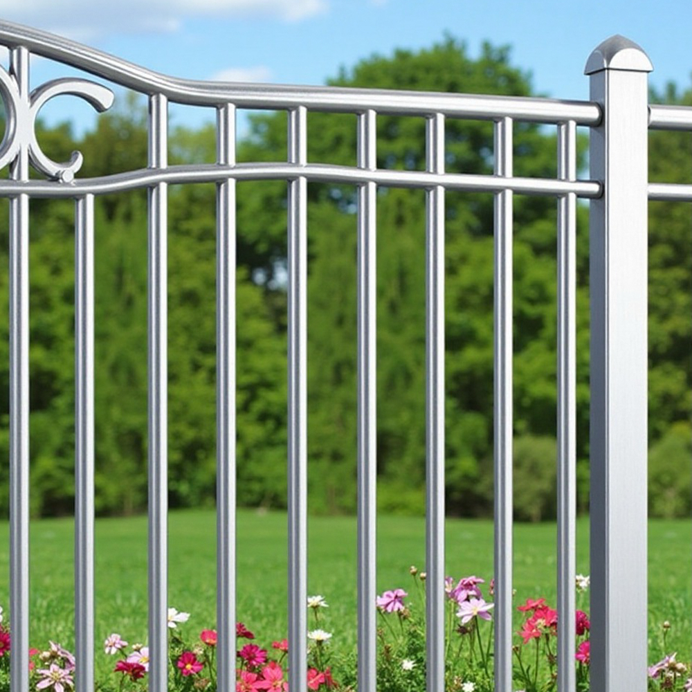
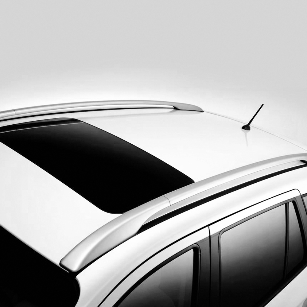
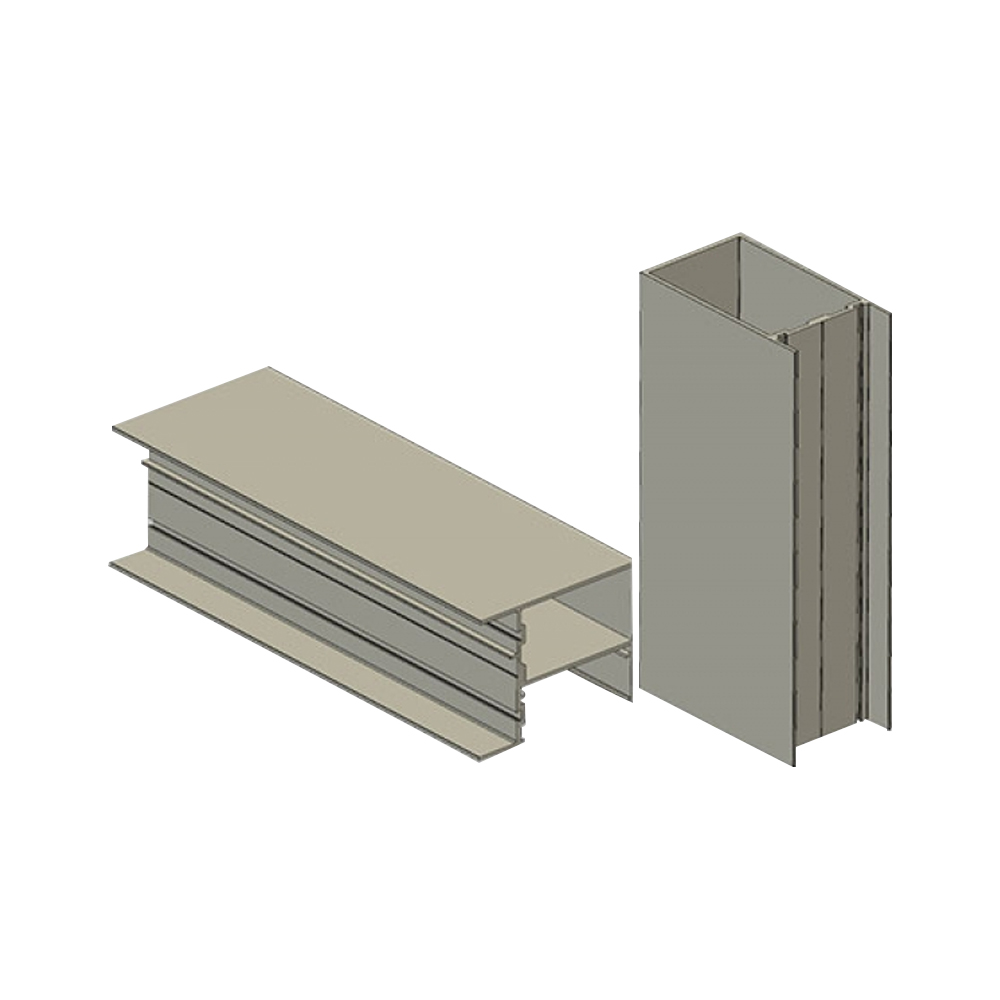
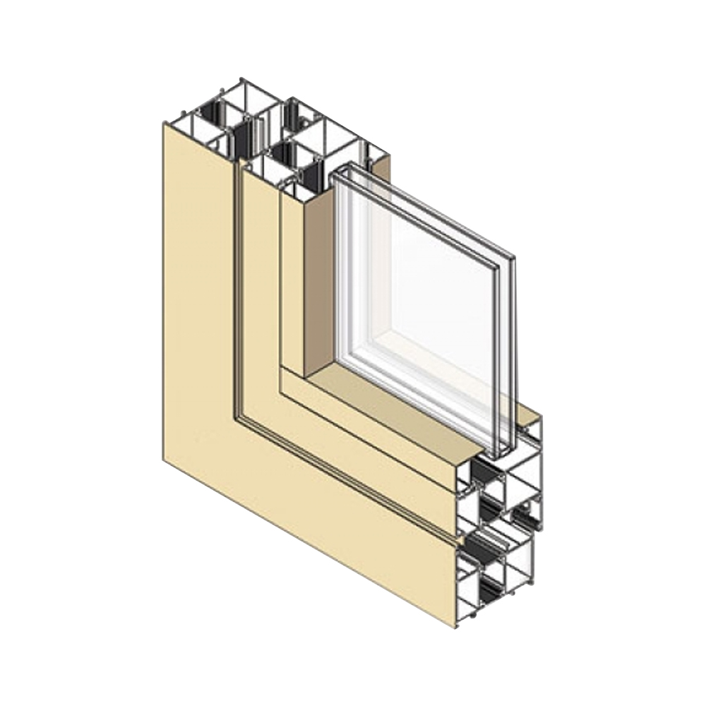
An aluminum extrusion profile is a linear structural shape produced by forcing a heated aluminum billet through a shaped die opening under high pressure, creating a continuous length of constant cross-section. The fundamental advantage of this process is that almost any cross-sectional geometry can be produced in a single piece, integrating fastening grooves, screw bosses, heat sink fins, hinges, and wiring channels directly into the profile, eliminating the assembly and welding steps that would be required with fabricated steel or machined components. The most commonly used aluminum alloys for architectural and structural extrusion are the 6000 series—predominantly 6060, 6061, 6063, and 6005A—which offer an optimal balance of extrudability, mechanical strength, corrosion resistance, and response to anodizing and powder coating. The selection of the correct alloy and temper for the application is the most consequential decision in extrusion design because it determines the profile's tensile strength, its surface finish quality after anodizing, and its behavior in the extrusion press, which directly affects the achievable tolerances and the cost per kilogram.
Content
- 1 The Extrusion Process: From Billet to Profile
- 2 Alloy Selection: The 6000 Series and Their Properties
- 3 Profile Design Rules: Wall Thickness, Tolerances, and Manufacturability
- 4 Surface Finishing: Anodizing, Powder Coating, and Mechanical Treatments
- 5 The T-slot and Modular Framing Ecosystem
- 6 Thermal Break Technology for Energy-Efficient Windows
- 7 Structural Design: Section Properties and Buckling
The Extrusion Process: From Billet to Profile
The transformation of a solid aluminum cylinder into a complex profile occurs in a horizontal extrusion press. A log of aluminum alloy, typically 150 mm to 300 mm in diameter and cut into billets 600 mm to 1200 mm long, is preheated in an induction or gas-fired furnace to a temperature between 430°C and 500°C, placing the metal in a plastic, malleable state below its melting point. The heated billet is transferred to the press container, where a hydraulic ram—capable of exerting forces from 1,000 to over 10,000 tonnes—forces the aluminum through the die orifice at the container exit. The extrusion ratio—the cross-sectional area of the billet divided by the cross-sectional area of the profile—typically ranges from 10:1 to 80:1 for architectural profiles, though ratios up to 200:1 are achievable for simple solid shapes.
As the metal passes through the die, it undergoes severe plastic deformation that aligns the grain structure of the alloy with the extrusion direction, imparting anisotropic mechanical properties. The extruded profile exits the die at a temperature close to the billet preheat temperature and at a speed that varies with the alloy and the profile complexity—from 2 to 5 meters per minute for soft 6060 alloy in simple shapes, down to less than 0.5 meters per minute for hard 7000 series alloys in thin-walled complex sections. The profile is cooled immediately after exiting the die, either by forced air or water spray, to freeze the microstructure before grain growth can occur. The profile is then stretched by a controlled amount—typically 0.5% to 2% elongation—to straighten it and to relieve the residual stresses locked in during cooling. Finally, the profiles are cut to length and age-hardened in an oven to precipitate the strengthening phases that develop the alloy's specified mechanical properties.
Alloy Selection: The 6000 Series and Their Properties
The 6000 series aluminum alloys are age-hardenable materials whose primary alloying elements are magnesium and silicon, which combine during the aging heat treatment to form a fine dispersion of magnesium silicide (Mg₂Si) precipitates. These precipitates impede dislocation movement, providing the strengthening mechanism that raises the alloy's yield strength from its as-extruded condition. The ratio of magnesium to silicon, the total alloy content, and the aging parameters are the control knobs that differentiate the alloys within the 6000 family.
| Alloy | Temper | Tensile Strength (MPa) | Yield Strength (MPa) | Extrudability Rating | Anodizing Quality | Typical Application |
|---|---|---|---|---|---|---|
| 6060 | T5 | 160-215 | 120-180 | Excellent (100%) | Excellent | Architectural trim, decorative sections, thin walls |
| 6063 | T6 | 205-245 | 170-215 | Very Good (95%) | Very Good | Window and door frames, general construction |
| 6061 | T6 | 290-310 | 240-275 | Good (75%) | Good (may show die lines) | Structural frames, machine parts, heavy-duty fixtures |
| 6005A | T6 | 270-290 | 225-245 | Good (80%) | Good | Structural glazing mullions, bridge railings |
| 6082 | T6 | 310-340 | 260-290 | Moderate (60%) | Moderate | High-stress structural, vehicle chassis, shipbuilding |
The extrudability rating directly translates to extrusion speed and, therefore, cost. Alloy 6060 extrudes rapidly with minimal die wear and can achieve the thinnest wall sections, making it the most economical choice where strength requirements are modest. Alloy 6082, at the other extreme, requires higher billet temperatures, slower extrusion speeds, and more frequent die replacement, increasing the profile cost by 30% to 50% compared to an equivalent 6060 profile. The selection principle is to choose the lowest-strength alloy that meets the structural requirements, unless the surface finish quality—particularly for anodized architectural applications—dictates a cleaner alloy like 6060 or 6063.
Profile Design Rules: Wall Thickness, Tolerances, and Manufacturability
Designing an aluminum profile for extrusion requires adherence to geometric rules that ensure the profile can be produced consistently, economically, and to the required tolerances. The most fundamental constraint is minimum wall thickness, which is determined by the circumscribing circle diameter (CCD)—the smallest circle that completely encloses the profile cross-section. For a profile with a CCD of 100 mm, a minimum wall thickness of 1.5 mm to 2.0 mm is typically achievable in 6060 alloy, increasing to 2.5 mm to 3.0 mm for 6061. Thinner walls are possible—down to 1.0 mm for small profiles in 6060—but they increase the extrusion pressure and reduce the die life. The general rule is that the ratio of the wall thickness to the circumscribing circle diameter should be no less than 1:40 for 6060 alloy and 1:25 for 6061.
Sharp internal corners concentrate stress in the die and in the extruded profile and must be radiused. A minimum internal radius of 0.5 mm to 1.0 mm is standard, with larger radii preferred for alloys with lower extrudability. External corners can be sharper—a radius of 0.3 mm is achievable—but a radius that is too small will cause the die edge to wear rapidly, resulting in a "washout" where the corner becomes progressively more rounded over the production run. Hollow profiles require a bridge or porthole die that divides the aluminum flow around a mandrel, and the weld lines where the divided streams rejoin must be considered in the profile's structural design; the longitudinal weld strength in a properly extruded hollow profile is approximately 85% to 95% of the base metal strength for 6000 series alloys.
Tolerances for aluminum extrusions are defined by EN 755-9 in Europe and ANSI H35.2 in North America, with the tolerance band depending on the dimension and the profile's circumscribing circle. A typical dimensional tolerance for a cross-sectional dimension under 100 mm is ±0.3 mm to ±0.5 mm, widening to ±0.5 mm to ±0.8 mm for dimensions between 100 mm and 300 mm. Angular tolerances are typically ±1° to ±2°. Tighter tolerances can be achieved—and should be specified on the engineering drawing—but they increase the die cost and the scrap rate. The profile designer should specify the tolerance on the drawing rather than relying on the default standard, and the tolerance should be no tighter than the function genuinely requires.
Surface Finishing: Anodizing, Powder Coating, and Mechanical Treatments
Aluminum extrusion profiles are rarely used in their as-extruded mill finish condition for architectural applications. The surface is transformed by a sequence of chemical and mechanical treatments that provide corrosion protection, color, and texture. The two dominant finishing processes are anodizing and powder coating, each with distinct advantages and process requirements.
Anodizing
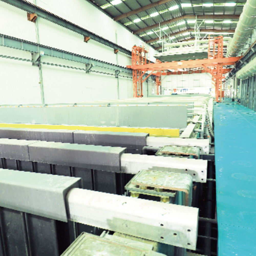
Anodizing is an electrochemical process that converts the aluminum surface into a controlled thickness of aluminum oxide (Al₂O₃) by making the profile the anode in an electrolytic bath—typically sulfuric acid—with a direct current applied. The oxide layer grows both outward from and inward into the aluminum surface, forming an integral ceramic coating that is 5 to 25 microns thick for architectural applications. The oxide is transparent, hard (approximately 350-400 HV on the Vickers scale), and microporous. The porosity is exploited in a subsequent sealing step—typically immersion in boiling deionized water or a nickel acetate solution—that hydrates the oxide and closes the pores, producing a corrosion-resistant, non-absorptive surface. The anodized finish is available in natural silver (clear anodizing), in a range of bronze and black tones achieved by varying the anodizing parameters and the alloy composition, or in electrolytically colored finishes where metal salts are deposited into the oxide pores before sealing.
The alloy selection critically affects the anodized appearance. Alloy 6060 with a controlled iron content below 0.25% produces the cleanest, most uniform anodized finish with minimal visible die lines or streaking. Alloy 6061, with its higher iron, copper, and chromium content, produces an anodized finish that is slightly gray and may exhibit a visible flow-line pattern that is unacceptable for decorative architectural applications. The standard for architectural anodizing is QUALANOD certification, which specifies the pretreatment, anodizing, and sealing process controls and the quality requirements for film thickness, sealing quality, and UV resistance.
Powder Coating
Powder coating applies a dry, electrostatically charged polymer powder to the aluminum surface, followed by oven curing that melts and cross-links the powder into a continuous film. The standard powder types for architectural aluminum are polyester and super-durable polyester, applied at a film thickness of 60 to 80 microns. Powder coating provides a wider color palette than anodizing—including bright colors, metallic effects, and textured finishes—and is more tolerant of minor surface imperfections in the substrate because the coating film fills and hides shallow die lines. The industry quality standard is QUALICOAT, which defines the pretreatment (typically a chrome-free conversion coating), the powder application and curing parameters, and the performance requirements for adhesion, impact resistance, and weatherability. Super-durable polyester powder coatings, qualified to QUALICOAT Class 2, are specified for exterior applications where color and gloss retention under UV exposure are critical, with a minimum Florida exposure rating of 3 years without significant degradation.
The T-slot and Modular Framing Ecosystem
A particularly significant category of aluminum extrusion profiles is the T-slot structural framing system, most commonly based on a square or rectangular profile with a longitudinal T-shaped slot on one or more faces. The slot geometry—a rectangular channel with a constricted opening—accepts a specially shaped nut that can be positioned anywhere along the slot and locked in place by rotating the bolt that engages it. This system allows structural frames, machine guards, workstations, and enclosures to be assembled without welding, without drilling, and with the ability to be reconfigured or disassembled. The standard T-slot series are sized by the profile's nominal width dimension in millimeters, with 20 mm, 30 mm, 40 mm, and 45 mm being the most common base dimensions, each with a defined slot width—typically 5 mm, 6 mm, 8 mm, or 10 mm—that dictates the compatible fasteners and accessories.
The T-slot profile is almost always extruded in 6060 or 6063 alloy with a T5 or T6 temper, as the slot geometry imposes a demanding die design—a cantilevered tongue of die steel that forms the slot undercut—that benefits from the softer, more easily extruded alloys. The modularity of the T-slot system is amplified by a vast catalog of compatible accessories: angle brackets, gusset plates, hinges, panel retainers, linear bearing rails, conveyor rollers, and mounting feet, all designed to engage the T-slot without modifying the profile. The design load capacity of a T-slot frame is determined by the profile's moment of inertia, the fastener clamping force, and the bracket strength. A typical 40x40 mm T-slot profile in 6060-T5 has a moment of inertia Ix of approximately 6.5 to 9.0 cm⁴ depending on the wall thickness, giving it a mid-span load capacity of several hundred kilograms over a 1-meter span before exceeding the deflection limit of L/300 typically used for frame structures.
Thermal Break Technology for Energy-Efficient Windows
Aluminum is an excellent thermal conductor with a thermal conductivity of approximately 160 W/m·K for the 6000 series alloys, which makes an unbroken aluminum window frame a thermal bridge between the interior and exterior environments, leading to condensation on the interior frame surface and significant heat loss. The solution is the thermally broken aluminum profile, where the single aluminum extrusion is replaced by two separate extrusions—one facing the exterior, one facing the interior—joined by a structural insulator, typically a glass-fiber reinforced polyamide (PA66) strip. The polyamide strip is inserted into longitudinal grooves in both aluminum profiles and rolled or crimped in place, creating a continuous structural connection with a thermal conductivity of only 0.3 W/m·K, which is approximately 500 times lower than the aluminum it separates.
The overall U-value of a thermally broken aluminum window frame depends on the depth of the polyamide strip and the complexity of the extrusion profiles, which can incorporate multiple insulating chambers. A modern thermally broken window profile with a frame depth of 70 mm to 90 mm and a triple-pane insulating glass unit can achieve a whole-window U-value of 0.8 to 1.2 W/m²·K, meeting the Passive House standard of 0.8 W/m²·K or below. The thermal break also shifts the dew point outward, so that under normal interior humidity conditions, the interior frame surface remains above the dew point and condensation is prevented. The structural integrity of the thermally broken assembly is verified by a shear test per EN 14024, where the polyamide strip must maintain its grip on both aluminum profiles under a tensile shear load of at least 24 N per millimeter of strip length.
Structural Design: Section Properties and Buckling
An aluminum extrusion used as a structural member—a beam, a column, or a frame element—must be analyzed for its section properties and stability under load. The primary section properties are the cross-sectional area, the moments of inertia about the principal axes, and the section moduli. Because aluminum's modulus of elasticity is approximately 70 GPa—roughly one-third that of steel—deflection, rather than stress, is often the governing design criterion for aluminum beams. The allowable deflection limit for aluminum structural members in building applications is typically L/250 for beams supporting plaster or brittle finishes and L/200 for beams supporting flexible finishes, per the Aluminum Design Manual.
Buckling is the critical failure mode for aluminum columns and for thin-walled profile elements in compression. The local buckling of a flat plate element—a flange or a web of an extruded profile—occurs when the compressive stress exceeds the critical buckling stress, which depends on the plate's width-to-thickness ratio and the edge support conditions. The Aluminum Association's Specification for Aluminum Structures classifies profile elements as stiffened (supported along both edges), unstiffened (supported along one edge only), or edge-stiffened, and provides limiting width-to-thickness ratios for each classification and alloy-temper combination. A designer seeking to optimize a profile for minimum weight will push the plate elements toward the buckling limit, accepting that the profile may be governed by stability rather than material yield.